Wiring a Telecaster
Note that Guitar Kits Direct Tele style guitar kit comes with all the wiring already pre-wired and assembled,
only the jack plug and ground wire to bridge need soldering, you can view photos by clicking the picture.
This article is to teach you the basics and give you an overview of how guitars are wired together.
WIRING A TELE
The Telecaster guitar has a spiky sound, with more highs and lows than other guitars. It is well
known for its bright and twangy sound that comes from the bridge pickup and solid body. It is loved
by many for its ability to play country, bluegrass, and even the blues.
TOOLS FOR THE JOB
First, we need to talk about the tools you will need for changing your electronics.
1 – Output jack
2 – 250K pots
1 – .050µF capacitor
1 – .001µF capacitor
1 – 3-way lever switch
1 – guitar wire 22AWG, white
1 – guitar wire 22AWG, black
1 – 25+ Watt soldering iron
1 – phillips screwdriver
1 – wire cutting and stripping tool
1 – rosin core solder
ASSEMBLING THE CONTROL PLATE
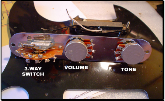
The first step will be installing the potentiometers and 3-way switch in the control plate. When
the control plate is upside down, the spring on the 3-way switch will be facing away from the
guitar body. Align the two pots so that the lugs are facing each other.

SOLDERING THE OUTPUT JACK
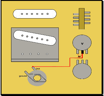
Next, we are going to solder the ground wire and hot wire to the output jack. In order to solder
properly, you should first add solder to each part that is getting connected. Then touch the two
parts together along with the soldering iron. Make sure both parts don’t move until they cool down,
or else you will get a bad solder joint. It should only take a few seconds for the parts to cool
down after they have been soldered.

Next, fish all of the wires through the holes in the body. Pull in the output jack wires you just
soldered, and screw down the output jack plate. Pull the bridge pickup wires through the hole
closest to the bridge. Pull the neck pickup wires through the hole closest to the neck. Also add
a black bridge ground wire that is going to go through the hole closest to the bridge. That wire
will connect the bridge to the volume pot. Each pickup has a hot wire and a black ground wire.
The output jack also has a hot wire and black ground wire.
SOLDERING THE PICKUP WIRES
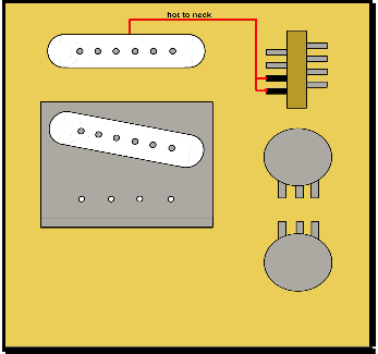
The next step will be to connect the hot wires from the bridge pickup to the top two lugs on the
right side of the 3-way switch. You can do this by twisting a small wire to the hot pickup wire. It
is much easier to solder one connection to one lug. So if several wires need to be connected to the
same lug or pot, twist them together before you solder them to the lug or case.


CONNECTING THE SWITCH TO THE VOLUME POT
Now you are going to connect the top left and bottom right lugs with a jumper wire. That wire will
connect to the left lug on the volume pot, and also to a small treble bleed capacitor. You will
have to twist a few wires together to do this. Make sure to cut and strip the wires to the correct size.

SOLDERING THE VOLUME AND TONE POTS
The next step involves soldering the hot wire from the output jack to the middle lug on the volume
pot. You will also be connecting the other end on the capacitor to that same lug.

Now you will connect the loose bridge ground wire to the right side of the volume pot. Solder it to
the metal casing. It will connect to another wire which goes to the right lug. That lug also will
connect to one of the prongs on the large capacitor. Before you do this, you will need to add
solder to the bottom of the volume pot case. Add solder to the left and right side.

Next you are going to connect the left lug of the volume pot to the left lug of the tone pot. Also
connect the right lug on the volume pot to the middle lug on the tone pot with a capacitor. You
will also need to solder a ground wire connecting both pots as shown in the picture. All pots will
need to be grounded, and all grounds will need to be connected to each other.

SOLDERING THE GROUND WIRES
Next, you are going to connect the three ground wires from the neck pickup, bridge pickup, and
output jack to the left side of the volume pot.

THE BRIDGE GROUND WIRE
The last step involves putting the black bridge ground wire through one of the screw holes in the
bridge. Wrap it around one of the screws and screw it down. This way it will stay in contact with
the bridge and won’t move.


Here is the finished wiring.


For more information on Do It Yourself Guitar Kits


